Light Sensor, Servo and Chat GPT
Thanks ChatGPT for making this project easy to complete! After reading this week’s assignment, I felt the dread of weeks past creep in. I have struggled with getting one component to work and now we had to program for two components, eek! However, as we were told in the assignment, ChatGPT is pretty amazing at writing code and laying out how to assemble the board. I was very specific in what I wanted and made sure that the bot knew that I was a complete novice at this.
Here is my chat with the bot:
Components:
Vilros Arduino board (e.g., Uno or compatible)
Servo motor (e.g., SG90)
Light sensor (e.g., photoresistor or LDR)
10kΩ resistor
Jumper wires
Breadboard
Power source for Arduino (e.g., USB cable)
Circuit Instructions:
Connect the Light Sensor (LDR):
Place the LDR on the breadboard.
Connect one leg of the LDR to the 5V pin of the Arduino.
Connect the other leg of the LDR to an analog input pin (e.g., A0) and one end of a 10kΩ resistor.
Connect the other end of the resistor to GND. This forms a voltage divider circuit, allowing the Arduino to measure light levels.
Connect the Servo Motor:
Connect the servo’s signal wire (yellow/orange) to a PWM pin (e.g., pin 9) on the Arduino.
Connect the red wire of the servo to 5V.
Connect the brown/black wire of the servo to GND.
Power the Circuit:
Ensure all components share a common ground (GND).
Connect the Arduino to your computer via USB for power and programming.
Arduino Code:
Here is a simple sketch to control the servo based on the light sensor's readings:
#include <Servo.h>

// Declare the servo object
Servo myServo;

// Define the pin connections
const int ldrPin = A0; // Analog pin for the light sensor
const int servoPin = 9; // PWM pin for the servo

void setup() {
  // Attach the servo to the specified pin
  myServo.attach(servoPin);

  // Initialize serial communication for debugging
  Serial.begin(9600);
}

void loop() {
  // Read the light sensor value
  int lightValue = analogRead(ldrPin);

  // Map the light sensor value (0-1023) to servo angle (0-180 degrees)
  int servoAngle = map(lightValue, 0, 1023, 0, 180);

  // Set the servo position
  myServo.write(servoAngle);

  // Debugging output
  Serial.print("Light Sensor Value: ");
  Serial.print(lightValue);
  Serial.print(" -> Servo Angle: ");
  Serial.println(servoAngle);

  // Small delay for stability
  delay(50);
}
How It Works:
The light sensor measures light intensity, producing a value between 0 (dark) and 1023 (bright).
The
map()function converts this value into a servo angle (0-180°).The servo moves to the corresponding angle based on the light level.
Testing:
Upload the code to your Arduino.
Adjust the light near the sensor (e.g., with a flashlight or by shading it).
Observe the servo moving in response to changes in light intensity.
This simple circuit demonstrates how to use sensor data to control a motor, providing a great foundation for more advanced Arduino projects!

Completed board
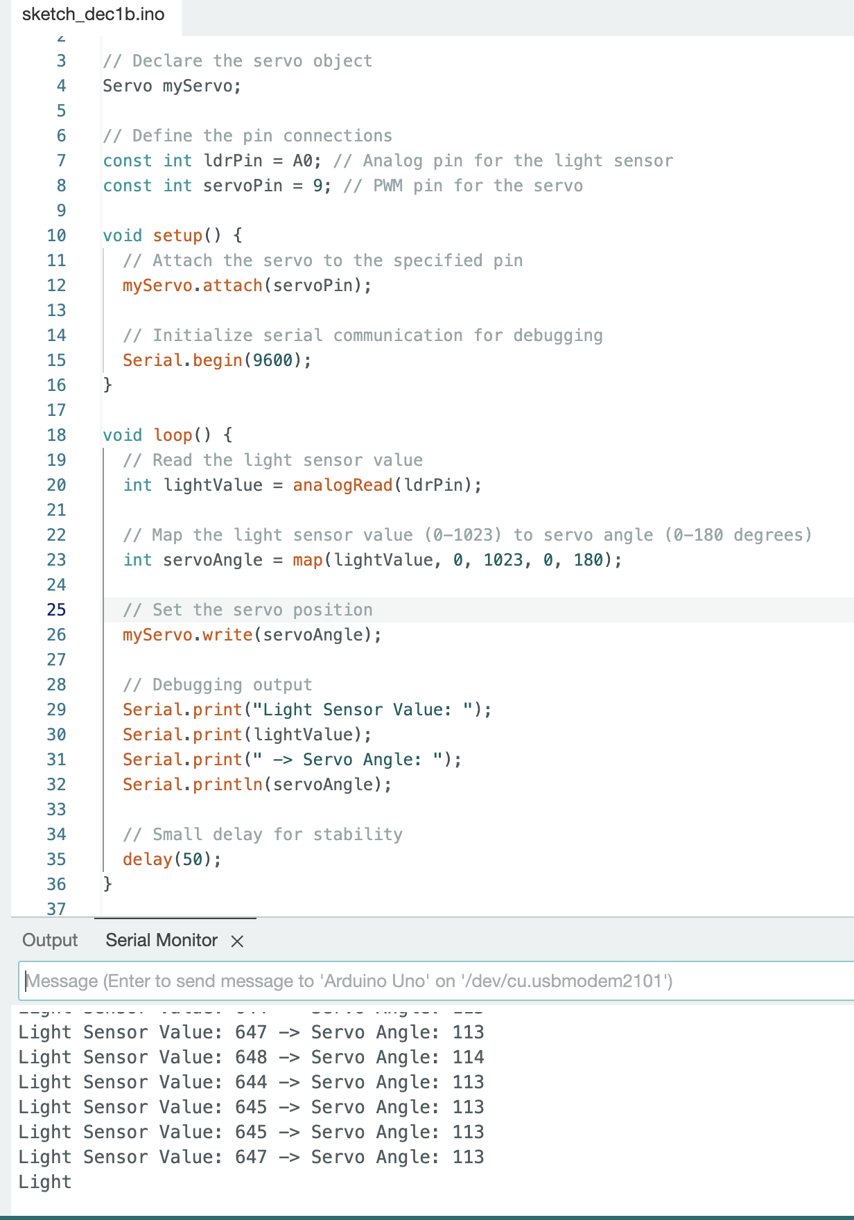
Completed Code